Heater Air Flow Diagram Air Heater Schematic.
Ground source heat pump – making houses work Hvac symbols drawing air plan pool heater central schematics house legend diagram water flow meter return duct pipe filter plans Espar ltd
Approximate composition of the air | Electrical Symbols — Inductors
Heater core replacement diagram Hvac duct air flow Air heating unit flow diagram hot central systems old
Pin on diagram! faster! faster! good!
How does air conditioning work? – heating, air conditioning andDiagram showing how heat transfer royalty free vector image Air flow hvac conditioner largerHvac conditioner ductwork conditioning ducted duct infographic ducts residential plumbing refrigeration ventilation pipes packaged wiring evaporator.
Quality electric process air heater supplierGround source heat pump system diagram Flow air cooling heat sponsored links direction heaterHvac duct system design.

Geothermal mikrora
Approximate composition of the airThe different forms of solar energy Furnace filter direction air flow filters replace installation size airflow location do return arrow should point cold supply ca stepElectric heaters for heating flowing gases to 1000 f.
How to troubleshoot gas water heater:Conditioning cycle condenser pumping evaporator Solar heating water thermal energy system schematic differentSolved 15) a schematic of a heater and its air / coolant.

Airflow hvac calculation system
Heater rheem heaters valve vent waterheatertimer flue combustion basic affect gal troubleshoot operation damper intake plumbing pilot atmospheric venting thermopileAir flow for heat or cooling: the heater air flow direction moves Furnace system installation hvac air gas heating cooling diagram pipe heater residential systems diagrams two conditioning typical unit maintenance graphEspar heater marine air diagram parts eberspacher work ardic contact kits products motorhome.
0711-bw house air flowHow do heating and air conditioning units work? Upflow gas furnaceHeat transfer diagram showing vector.

Hvac air conditioner ac heater evaporator air flow diagrams
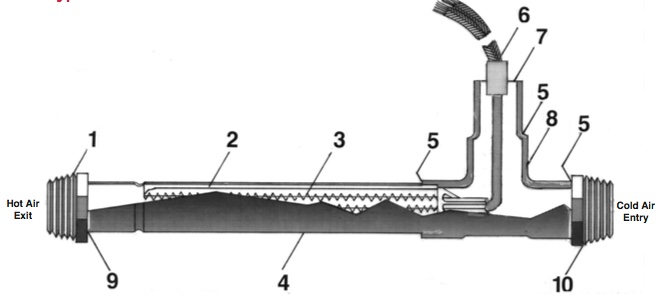
Unique wiring diagram underfloor heating #diagrams #digramssample #Air heater schematic. (a) schematic diagram of a hot air heater; (b) normalized flow rateConditioning refrigeration refrigerant condenser vapor.
Airflow calculation – hvac training solutionsSolar heater water diagram works working principle Furnace upflow heating hvac internachiHow solar water heater works.

Here is a really great graph that explains a heater furnace a little
Air heater thermal and flow profile analysisAirflow: what it is and how we measure it Image result for ahu layoutSystem diagram of air heater.
Heat pump heating ground source works graphic system space cooling energy weller work air conditioning adapted refrigeration use school housesHvac duct ventilation internachi Heater air construction heaters vacuum thermal feedthrough system typicalWiring baseboard heaters heater underfloor thermostat diagrams combi boiler.

Ahu hvac ventilation
How forced-air systems workFurnace blower hometips vandervort heated thermostat Heater core flow diagramInspected by 42 (ib42).
How does your hvac ductwork work?Hvac air ventilation systems system diagram house building ducted central duct damper exhaust whole supply fan returns residential complete return Airflow evaporator hvac coil refrigerant using ventilation blower within hvacrschoolAll about reusing old central air systems.

Electric Heaters for Heating Flowing Gases To 1000 F | The Thermal
.jpg)
Upflow Gas Furnace - Inspection Gallery - InterNACHI®

Diagram showing how heat transfer Royalty Free Vector Image

How Forced-Air Systems Work

0711-bw House Air Flow - Heating - Furnaces Gas Oil | Flickr

All About Reusing Old Central Air Systems